
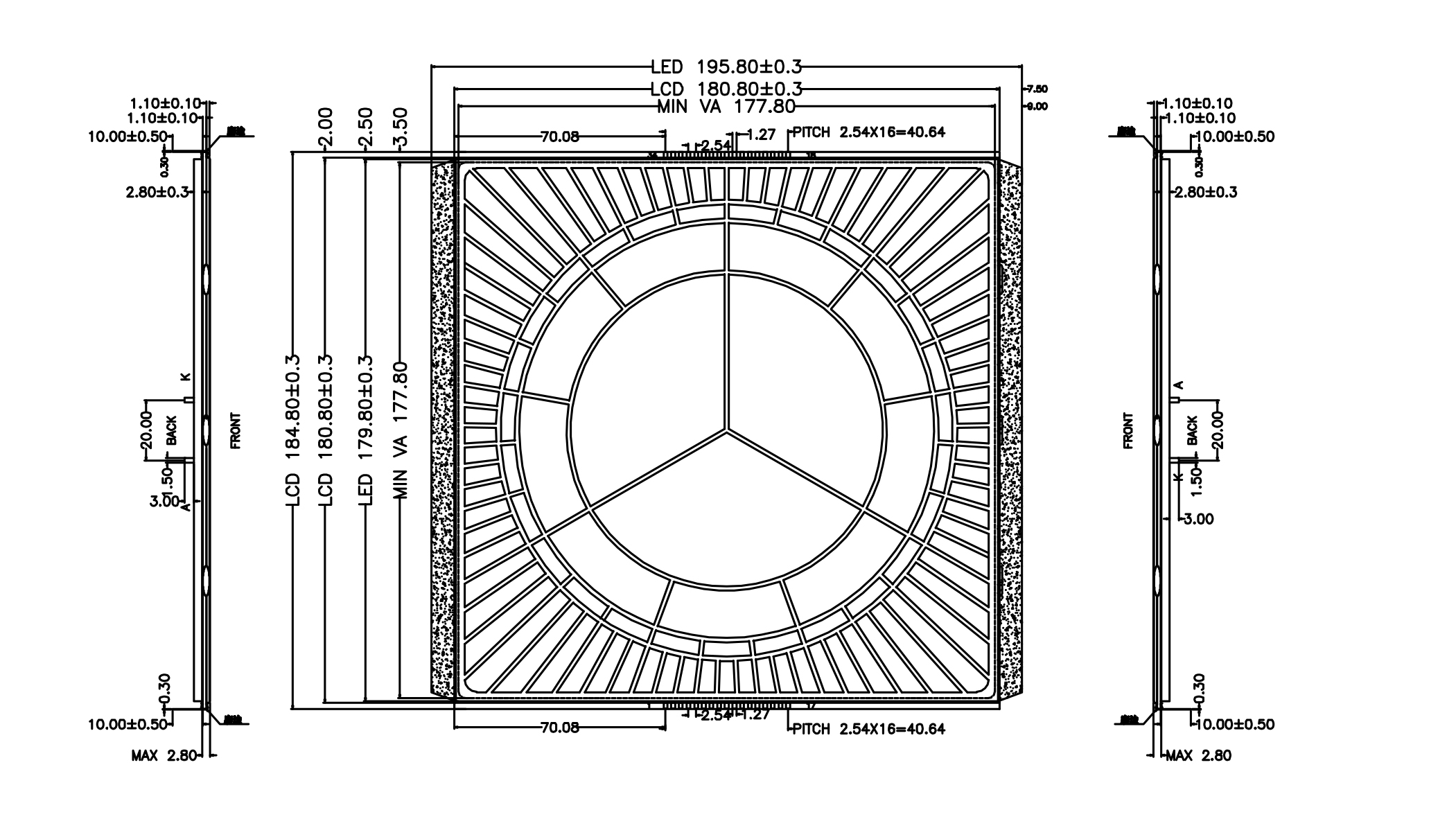
While I’ve been logging my progress on learning how to operate and interface with LCDs and segmented displays, I’ve been talking like someone who knows what they’re talking about. The thing is, I’ve been learning all of this on the fly. The whole point of all of it has been to order a custom made LCD display and I’ve finally put my money where my mouth is and invested $150 in non-refundable engineering costs. In honor of that, I wanted to break down what I’ve learned about what it takes to order a bespoke LCD.
Custom-built segmented LCD displays
The first place you need to start with ordering a custom LCD is with an idea. I’ve outlined my idea earlier, but in short, it’s a clock with a unique time system.
So I have the design I want and how I want it to perform. From here it should be simple right? lol
Once you have the design nailed down, you’d think the next thing to do would be to find a supplier, and that sounds reasonable, but what you really need to do is get learnt about LCD displays and how they work. I’ve been documenting part of that journey here, but learning how to operate a segmented LCD display with a microcontroller is just half of the journey, you also need to know about the different types of LCDs and a lot of the terminology that’s used to describe their properties, because every supplier you contact is going to ask you.
The basics of segmented LCDs
The first thing a lot of suppliers asked me was about the connection. Pin is the most common and it’s what I went with, but a flexible ribbon connection is an option as well. Your pin count is dictated by the number of segments you have. With my 120-segment design, I had a couple of options. The seemingly simplest solution would be to have one pin for each segment, leaving me with 121 pins (120 segment-input pins and 1 common pin). And while there are LCD controllers out there with over 120 output pins, I want to stick with chips that are easy to find.
Pins and duty cycles
So if 121 pins is out, what’s more manageable? Just by asking that question, we have to dive into something called duty cycle. If each segment isn’t going to have a dedicated pin to drive it, then it has to share pins, which means we have to engage in some time-division multiplexing to achieve the appearance of a constant display. The duty cycle is how long each group of segments gets attention from the LCD controller. A duty cycle of 1/2 means that you can address half of the segments at any one time. Likewise, a duty cycle of 1/4 means that you can address a quarter of the segments at any one time. The duty cycle also represents the fraction of time that any segment is “on” during a cycle of the controller.
How do the pin count and duty cycle connect? Your minimum pin count is your segments multiplied by the duty cycle, plus the denominator. So for a 120 segments at 1/2 duty cycle I would need 62 pins. I plan on using the HT1621 chip for my LCD driver and it supports 1/2, 1/3, and 1/4 duty cycles and up to 128 segments. So, for my 120 segment display at 1/4 duty cycle, I would need 34 pins. I could drive that number lower with a different controller that supports a 1/10 or 1/12 duty cycle leaving me with 22 pins, but lower duty cycles come at a cost.
As you drive the duty cycle down, you also drive down the amount of time a segment is displayed and the amount of voltage it receives. This means that both the contrast of the segments and their viewing angle are reduced. Since the segments are receiving reduced voltage, that also means you might have to bump up your voltage. I’m trying to keep mine at 3.3 volts, in line with what the ESP32 can output.
Biting into bias
Bias is a complicated beast to tame, but it’s something you’ll be asked about, so I’ll do my best to partially untangle it. The first thing to know is that LCD demands AC power. You can run it off of DC power, but doing so for too long will permanently damage the display. To minimize damage on LCD displays, you have to constantly flip the direction of the power.
So, let’s assume a simple two-segment LCD display with two segment pins and one common pin. To light the first segment we need to apply a square wave of AC alternating between positive and negative voltage to its pin, and at the same time apply the inverse of that square wave to the common pin. This will ensure there’s always a voltage difference at that pin. Assuming we don’t want the second segment to display, we would have to apply the same inverse square wave to its pin as we do the common pin, ensuring that there’s zero voltage difference.

Now, let’s make this a tad more complicated with two segment pins and two common pins. Again, assume that we only want to display the single segment. Which square wave should we apply to Com2 to ensure only the one segment is displayed?
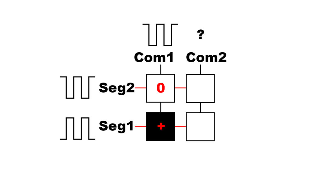
You can probably see the problem. If we apply the same “inverted” square wave to Com2 that we applied to Com1, Seg1Com2 will be displayed. If we apply the “normal” square that we applied to Seg1, then Seg2Com2 will be displayed.
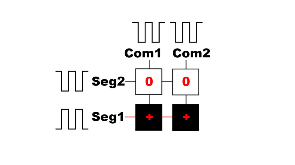
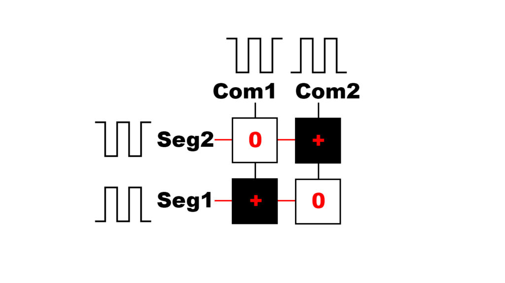
The solution to this conundrum is to apply an intermediate signal to Seg2 and Com2 (a flat wave, or constant input, in our thought experiment). With this solution, one of the segments is receiving a full voltage differential, two are receiving a half differential (which shouldn’t be sufficient to display the segment), and one is receiving none.
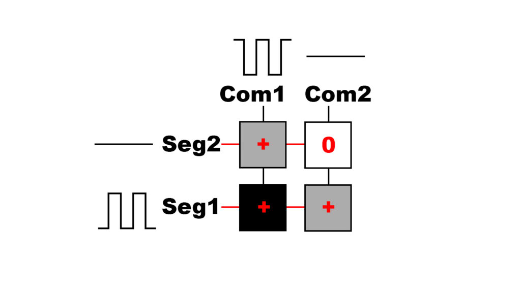
This is a gross oversimplification (and should illustrate why you need a special chip to control an LCD) but hopefully it gets the point across. Imagine how complicated this gets with lots of segments that need to be displayed within a 4 × 30 matrix. The above example is a bias of 1/2. With bias of 1/n you have n+1 voltage levels and n-1 intermediate voltage levels between high and low. There’s some complicated math behind the ideal bias for a particular duty cycle, and in the case of a 1/4 duty cycle, that ideal bias is 1/3.
Viewing angle and other details
Suppliers are also going to want to know the viewing angle for your display. Unlike many of the displays you’re used to, segmented LCDs have an ideal viewing angle and can segments can seem to disappear when viewed from a poor angle. For whatever reason, the industry standard when talking about viewing angle is to use the hours on a 12-hour clock face. So if you want your ideal viewing angle to be from the top, you want 12 o’clock. Since I want my clock to be on a wall, I went with 6 o’clock.
You have to decide if you want your display to be transmissive, reflective, or a little bit of both. Transmissive displays need a backlight whereas reflective displays rely on ambient light. The middle ground is a transflective display which combines the best of both worlds.
The last consideration I’ll mention is a positive versus negative display. A positive display has dark segments on a light background while a negative display has the opposite. My original design has black segments, so I went with a positive display.
What’s next?
Now that my supplier has my specifications and my money, I wait. The next thing they’ll deliver to me are the technical drawings, similar to what you’d see in a datasheet. Once I approve the drawings, they will go ahead with the engineering required to make a small test batch of displays. I’ll have to pay the shipping to get them to me in Mexico, but the cost of the sample run is included with the one-time $150 fee. In the meantime, I’m going to keep learning.
If you like what I do, send me $1 to help pay for the infrastructure!
Leave a Reply