

I’m going to make a one-of-a-kind clock using a custom LCD display. One of the issues I have to overcome to accomplish this is understanding the electronics and programming I’ll need to make it all work. Since I need to know how to manipulate segmented displays, the first stop on my journey is the 5161AS 10-pin, 8-segment, 1-digit LCD display that came bundled with my off-brand Arduino starter kit.
Exploring the 5161AS
When it comes to electronic components, the first thing you have to do is figure out what you have. In my case, I have a pair of 8-segment LCD displays, the simplest of which is the 5161AS.

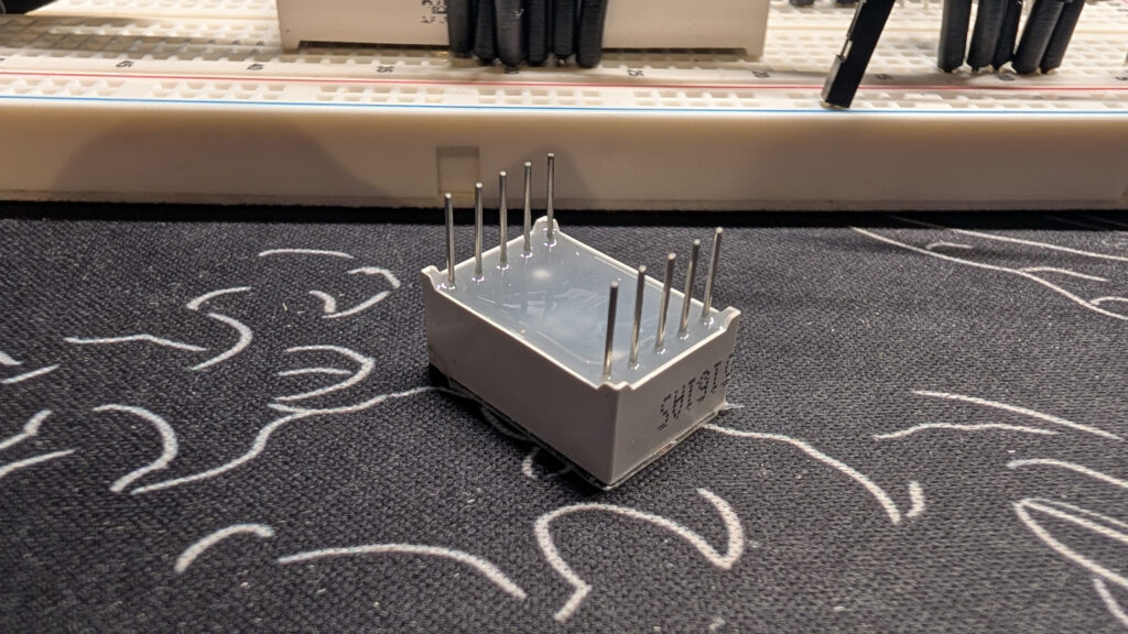
Unless you’re an old hand at this kind of thing (I am not), you’re going to want to dig up the data sheet for your component so you know how to use it without breaking it. Thankfully, the data sheet for the 5161AS is easy to find.
So what’s in the data sheet? What’s important? It depends on your component. Let’s dip into this one to pull out the relevant bits we need to start playing with it.
For me, the first thing I want to know when playing with a new component is what all the pins do. That information is on page 2 of the data sheet:

Admittedly, this schematic is a bit arcane if you’ve never seen something like it before, but it’s pretty clear once you know what you’re looking at. Those triangles are the standard symbols for diodes, of which our little display has eight. The numbers at top and bottom refer to the physical pins on the 5161AS. The letters refer to segments on the display.
Diodes (in this case light-emitting diodes) only allow power to flow in one direction (the direction the arrow is pointing) so we know we’re going to have to supply power to the eight pins on the bottom of the schematic. The 3 and 8 at the top of the schematic are the two cathode pins. You can see from the first page of the data sheet that this is a “common-cathode” component, which means that the LEDs don’t have individual cathodes, and it doesn’t matter which of the two pins we wire to ground.
So, where is pin 1 on the component, and how do those letters map to the segments on our display? The data sheet has you covered once again:
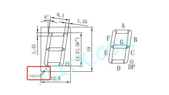
You can see the location of pin 1 marked in the bottom left beneath the dimensions of the display segments, and you can see the letters mapped to the segments on the right. Every 7-segment display I’ve come across uses the same convention for labeling their segments.
Now we know where pin 1 is, how do we know where the rest are? The standard convention for pins is that they proceed from pin 1 counterclockwise when viewing the component from above. So the pins on the bottom will be 1, 2, 3, 4, and 5 from left to right, and on top they will be 10, 9, 8, 7, and 6. With all this knowledge in hand, we’re almost ready to power this bad boy up.
The last question we need to answer from an electronics standpoint is “How much power does it need?” In this case, the answer is on page 3 of the data sheet:

The 5161AS is expecting to get 10 mA of current at 1.8 V. We know that the GPIO pins of an ESP32 output 3.3 V of power, which is too much for our single-digit display, so we’re going to need some resistors to make sure we don’t fry our LEDs. Let’s do some algebra!
Thanks to Ohm’s law we know that voltage (V) is equal to current (I) multiplied by resistance (R).
To figure out how much resistance we need, we need to first get the difference between how much voltage we’re outputting and how much voltage the display is expecting. That’s how much voltage we need to “burn off” with a resistor.
Now we can plug in that 1.5 V along with the 10 mA of current.
And with the magic of algebra, we can figure out how much resistance we should put into our circuit.
Which leaves us with 150 Ω. I don’t have any 150 Ω resistors, but that’s okay. The 5161AS actually accepts a range of current. Lower down on the third page of the data sheet you can see its maximum current draw.

If we drop that number into our resistance equation we get
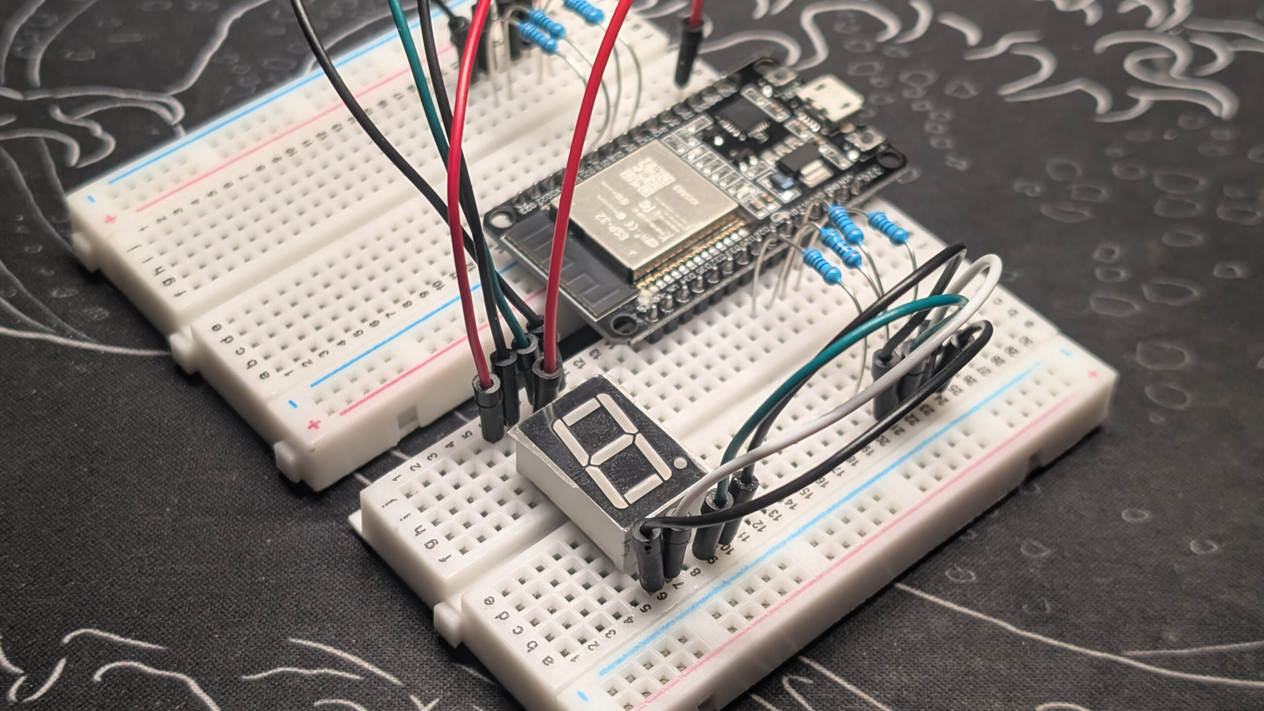
That means we can safely use any resistor between 50 Ω and 150 Ω to ensure our display has optimal power. I’m using 100 Ω resistors because that’s what came in my Arduino starter kit. Here’s what that circuit looks like:


At this point, if I set all eight GPIO pins to HIGH, all of my segments will light up. To make it display a number other than 8, we’ll have to write some code. In the meantime, here’s a little app to help you figure out how much resistance you might need:
Read next …
Read previous …

Buy somethin’ will ya!
If you like what I do, send me a dollar to help pay for the infrastructure!
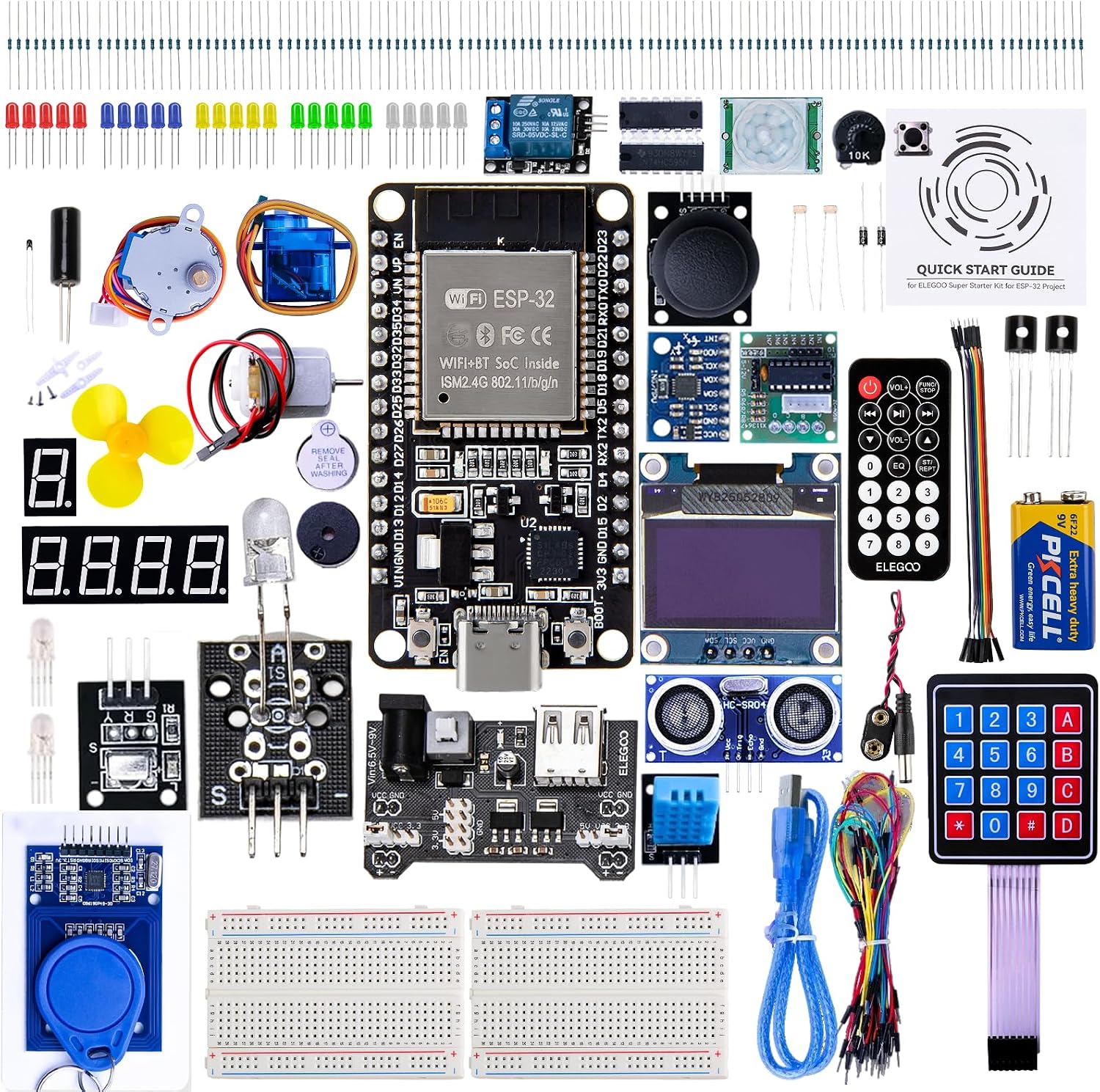
ELEGOO ESP-32 Super Starter Kit
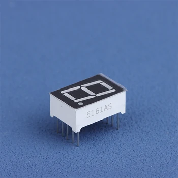
10Pcs 5161AS LED Display
Leave a Reply