
Even though my ESP32 dev board has enough GPIO pins to operate the 12 pins of the 5461AS LED display, it doesn’t leave many extra, and I can imagine a scenario where I’d want to maximize my GPIO availability, like a 120-segment clock. There are microcontrollers out there that have 120+ GPIOs, but since my eventual goal is to share my creation with other people, I want to use drop-in parts to make it easy for others to make themselves.
The simplest beginner tool for freeing up more pins is a shift register, and most beginner kits include one in the bundle of components they come with. The one I have is the SN74HC595. All of those letters and numbers mean something, but it’s easier to say it’s an 8-bit, serial-in, parallel-out shift register. You send it 8 bits of information (1 byte) over a data line (serial-in), and it will pull eight of its pins either high or low depending on the bits you sent it (parallel-out).
Hooking up the 595
Let’s take a look at its pinout and figure out what we’re working with.
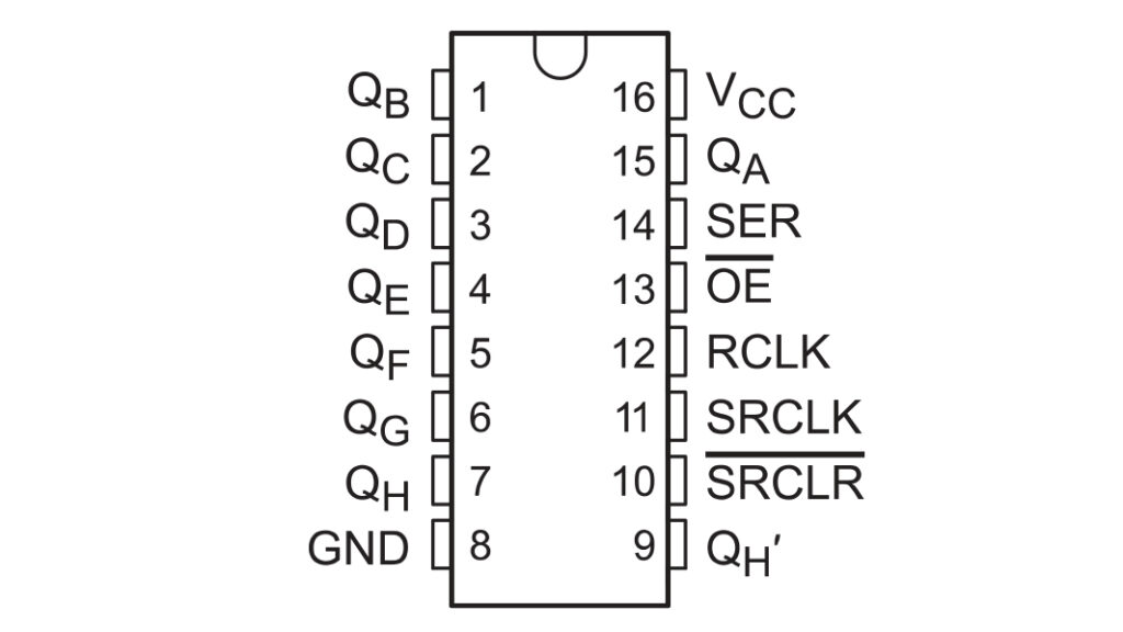
So, remember how I said this would pull eight pins up or down based on a byte that we sent it? Those output pins are QA–QH, or pins 15, and 1–7.
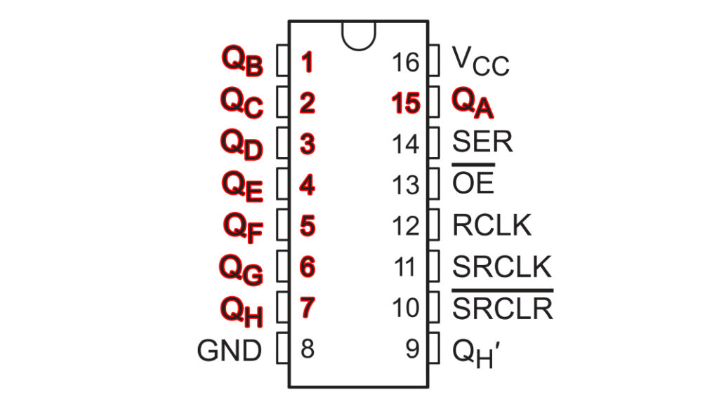
Since the 595 is going to hold those pins, it needs to have its own power source and ground.
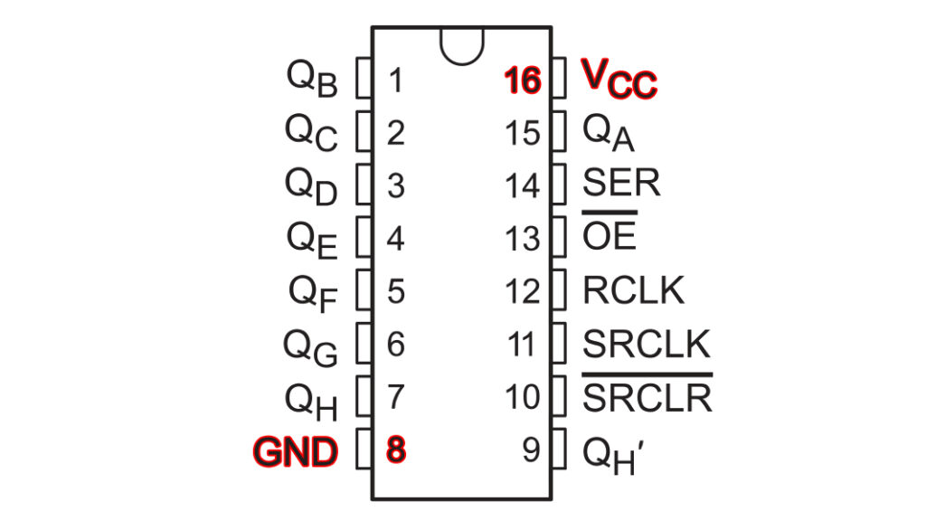
Of course we need a way to get our data into the 595, that’s what the serial input pin is for.
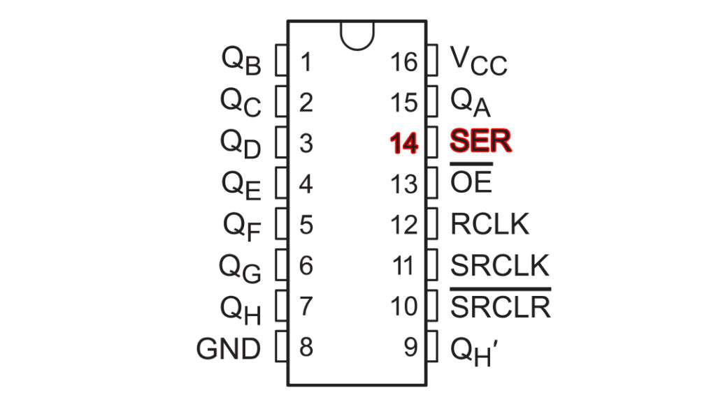
The 595 can’t make sense of the bytes we send it without two clock pins that let the IC know when it’s receiving data and when it should output the data it has. That’s what the serial clock and register clock (often called a latch pin because it locks in the data) pins are for.
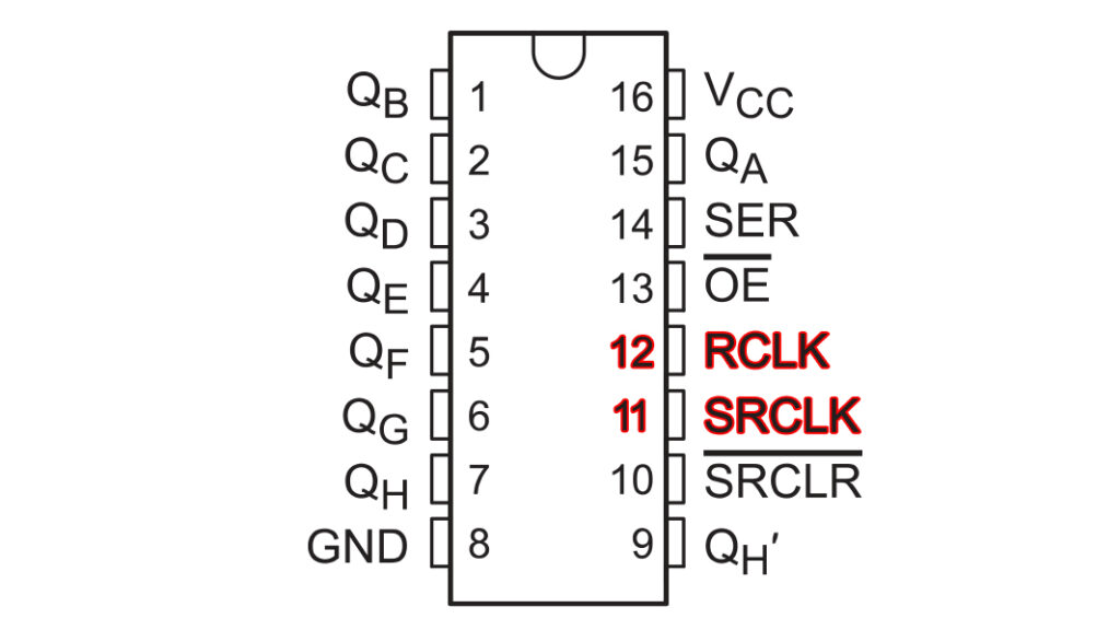
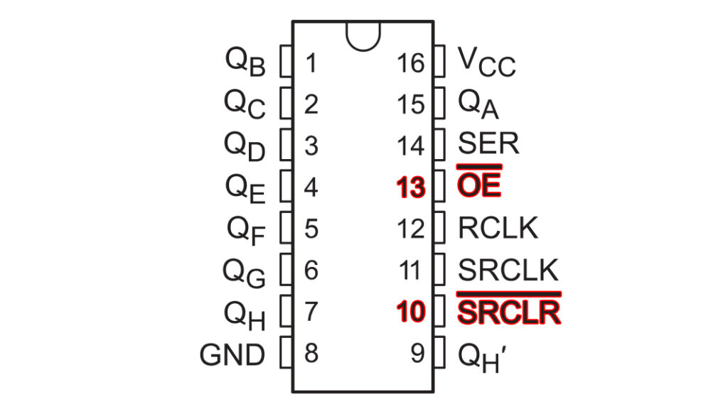
The bars over the OE and SRCLR pins indicate that their functions are activated when their line is pulled low. Output enable is kind of like a power switch for the output pins; keep it low to keep your outputs on. Serial clear is a quick way to reset all the output pins to low.
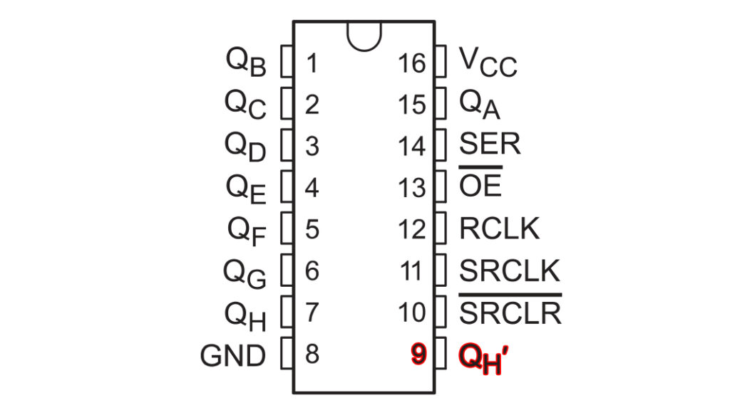
Finally, there’s QH’, which lets you chain multiple 595s together by outputting any extra bytes you’ve sent. I’m going to experiment with that later since I have an extra 595, but for now, I just want to get one working.
Before we dive into writing the code to make this thing work, let’s take a look at some more of the data sheet so we don’t get any surprises. The “Recommended Operating Conditions” is probably a good place to start.
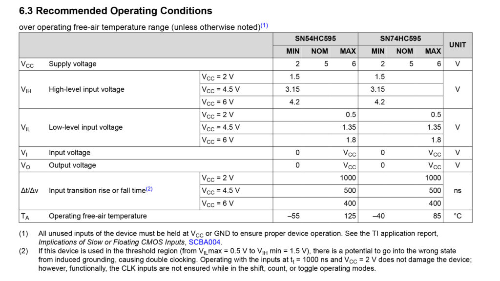
The first thing to take notice of is how much voltage it’s expecting.
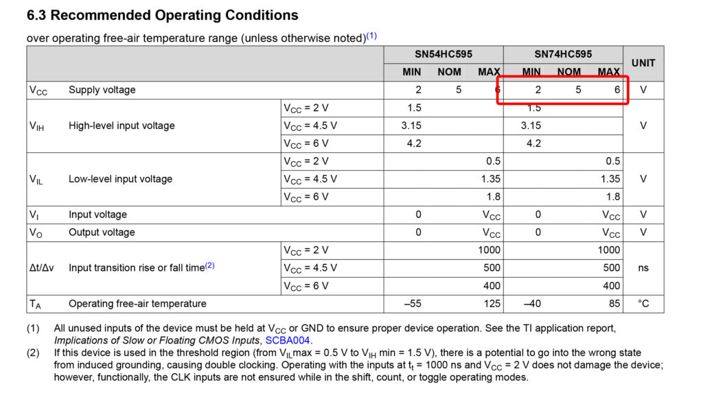
No fewer than 2 V and no more than 6 V with 5 V being nominal. Most tutorials you read on the 595 will tell you to power it with 5 V, and while the data sheet seems to agree, we need to think critically about the next rows on the sheet before we commit to running this thing from the 5 V pin or the 3.3 V pin.
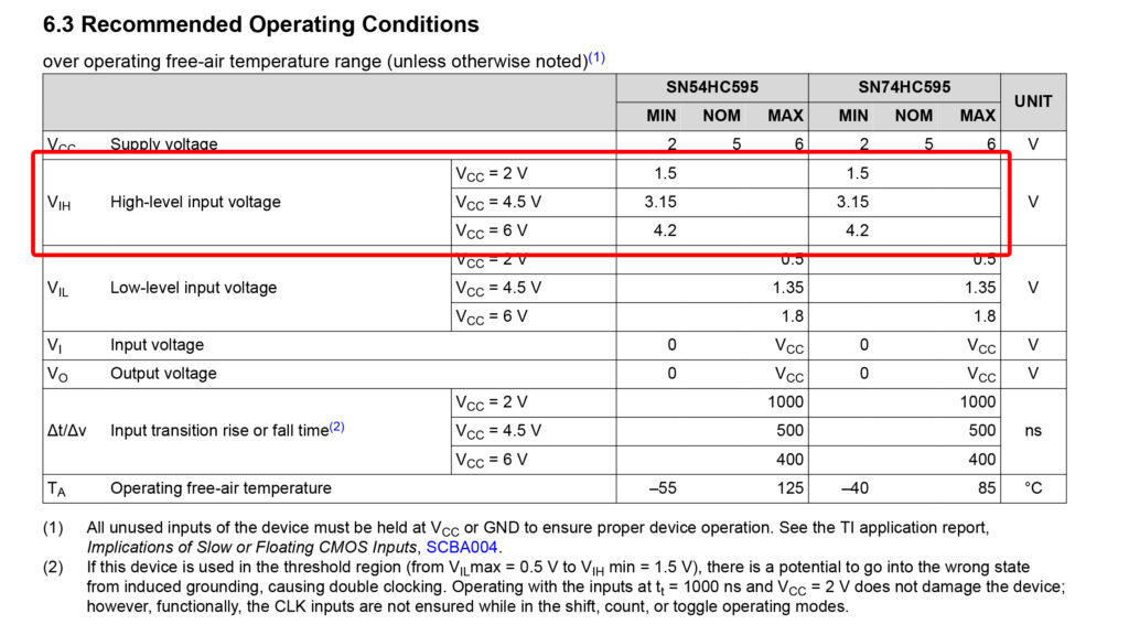
When we send our data to the serial pin or clock pins, it will be via 1s and 0s represented by high and low electrical signals. The highlighted rows above show the minimum voltage the 595 needs to receive on its pins to register as a high input. Notice it’s different depending on how many volts we’re sending to the chip.
Our operating voltage options of 3.3 V and 5 V aren’t listed on the chart, but we can get a rough idea based on the numbers we have. 1.5 V is 75% of 2 V, and 3.15 V and 4.2 V are 70% of 4.5 V and 6 V. Let’s plug in those numbers and see whether it’s more optimal to send 5 V to VCC (as most tutorials recommend) or 3.3 V.
If we send 3.3 V (which is what we have been using in our projects so far), we can expect a minimum threshold to register a high input between 2.31 V (70% of 3.3 V) and 2.475 V (75% of 3.3 V). On the other hand, if we send 5 V, those numbers jump to 3.5 V and 3.75 V. The thing is, the ESP32 has a max output of 3.3 V on its GPIO pins, so if we power it with the 5 V pin, there’s a good chance the 595 won’t be able to pick up the signals we’re sending it.
Next, take a look at the input and output voltages.
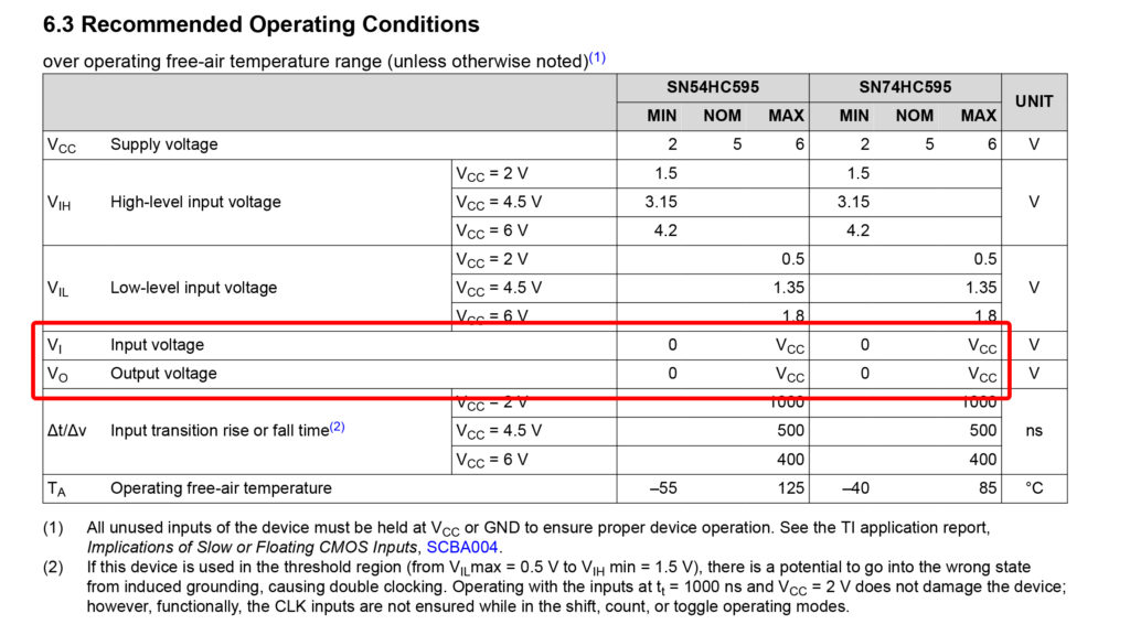
This is another reason to not use 5 V power on the 595 when using an ESP32. If you’re sending 5 V to the VCC pin, the 595 is going to expect 5 V on its serial and clock pins, and the ESP32 only outputs 3.3 V.
The last two columns we don’t have to worry about too much. We don’t have a lot of control over how fast our pins turn on and off, and if we’re working in temperatures outside the minimum and maximum, we’d have bigger problems to worry about.
There are some other interesting tidbits in the data sheet, but for now, let’s get this wired up so we can figure out how to use it. A quick note so you don’t make the same mistake I did. To keep the bytes you send to 595 more intuitive, I suggest outputting QA–QH to segments A–G + DP.
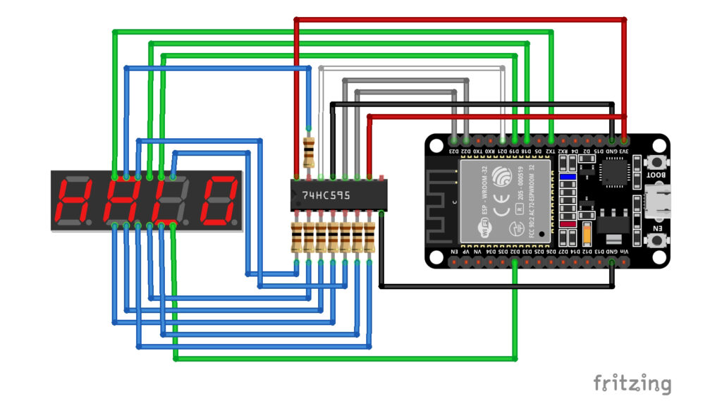
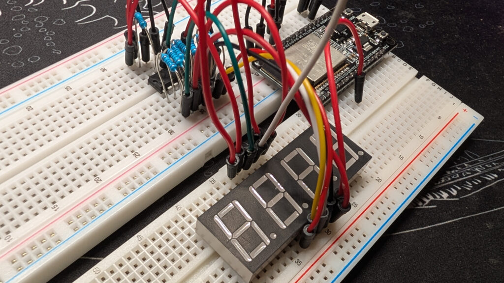
If you’re learning this at the same time as me, hopefully you found a way to make your breadboard not so crowded. Those bunched up resistors are killing me.
Read next …
Read previous …

Buy somethin’ will ya?
If you like what I do, send me $1 to help pay for the infrastructure!
ELEGOO ESP-32 Super Starter Kit
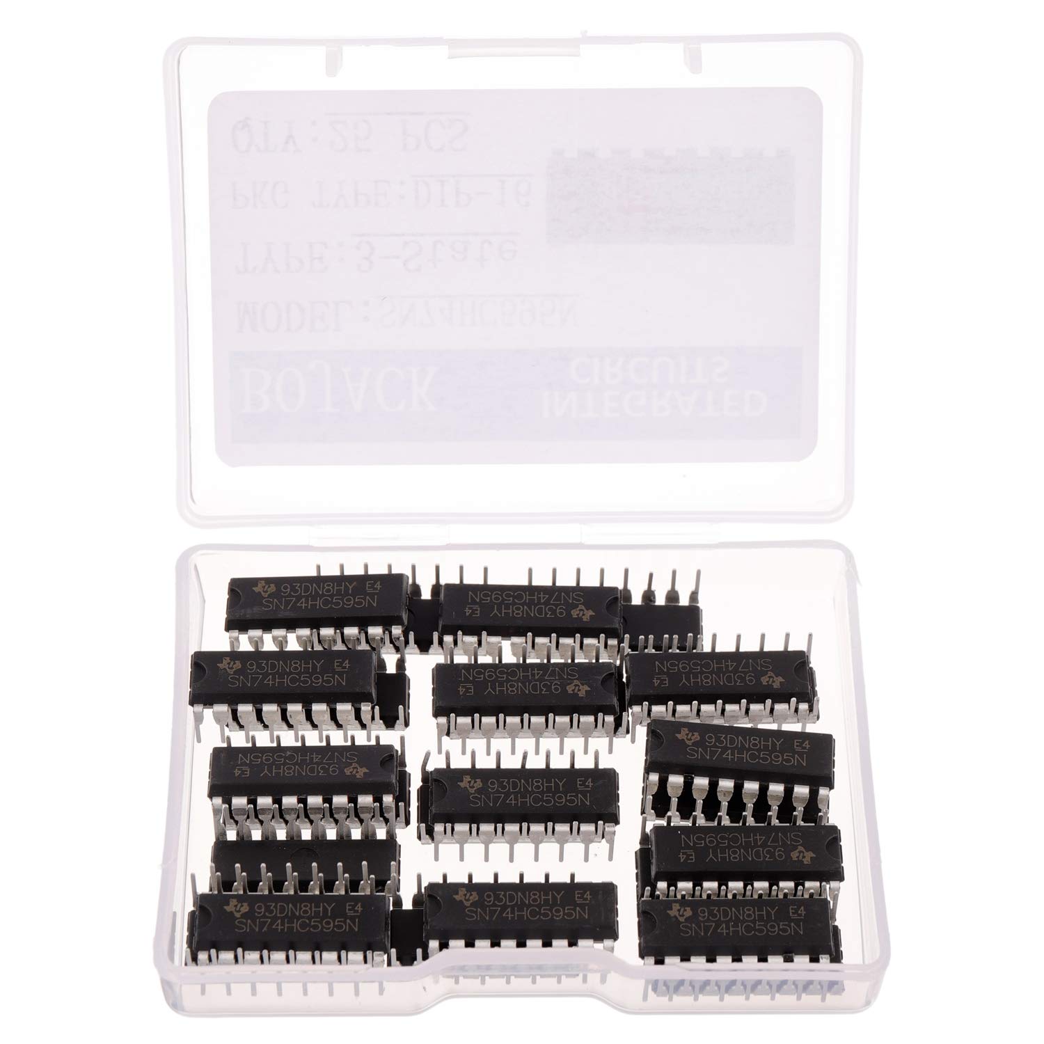
25-pack of SN74HC595N 8-bit shift registers
Leave a Reply