

We did the easy part by wiring up our TM1637. We did the hard part by making sense of what was in the data sheet. Now we just have to do the part that makes it do what we want: write the code.
In many ways, bringing the 1637 to life is a lot like using the 5461AS with the 595 shift registers. Instead of sending signals directly to the pins on our LED display, we’re sending signals to a bit of silicon that uses those signals to light up our LEDs. That means that we can reuse a lot of the code we did for that project.
Let’s start with the basics and define our DIO and CLK pins. Put them where you like on your ESP32, I opted for 22 and 23.
int DIO = 23;
int CLK = 22;Next, lets put in the bytes for the three commands we’re going to use.
int dataWrite = 0b01000000;
int addressC0H= 0b11000000;
int display = 0b10001111;We need some numbers to display, so to do that, we’re going to use a number array just like last time, but the 1637 expects to see the A segment of our LEDs as the least significant bit of the byte we send it (0 = –FEDCBA = 00111111). In our previous setups, the A segment was the most significant bit (0 = ABCDEF– = 11111100). What that means is we have to flip our number bytes around (or we could read them from left to right, you do you).
int nums[10] = {
  0b00111111,  // 0
  0b00000110,  // 1
  0b01011011,  // 2
  0b01001111,  // 3
  0b01100110,  // 4
  0b01101101,  // 5
  0b01111100,  // 6
  0b00000111,  // 7
  0b01111111,  // 8
  0b01100111   // 9
};Next, let’s take care of our setup() function. It needs to do a minimum of two things: set up the pin mode for our input pins,
void setup() {
	pinMode(DIO, OUTPUT);
	pinMode(CLK, OUTPUT);
}and pull them both to HIGH.
void setup() {
	pinMode(DIO, OUTPUT);
	pinMode(CLK, OUTPUT);
	digitalWrite(DIO, HIGH);
	digitalWrite(CLK, HIGH);
}If you remember from the previous post, in order to start sending commands to the 1637, we need to drop the data lines from HIGH to LOW. That means we need them to be in a HIGH state initially.
Next, we have to start our conversation with the 1637. The digital signal to prepare our driver to receive instructions is to first drop our DIO signal to LOW, followed by dropping the CLK signal to LOW.
void start() {
  digitalWrite(DIO, LOW);
  digitalWrite(CLK, LOW);
}Now that the 1637 is primed to listen for commands, we have to send it one in the form of an 8-bit signal. Sending our data over to the driver is essentially the same as sending bytes over to the 595, so the code will be very similar as well.
void sendByte(int data) {
  for (int i = 0; i < 8; i++) {
    digitalWrite(DIO, (data >> i) % 2);
    pulse(CLK);
  }
  pulse(CLK);
}In this implementation, we iterate over our byte, writing our DIO pin either high or low, then sending a CLK pulse to tell the 1637 to register that bit. Once we’ve sent that last bit, the action is a little bit different.
TM1637 data transfer carries with answering signal ACK. For a right data transfer, an answering signal ACK is generated inside the chip to lower the DIO pin at the failing edge of the 8th clock. DIO interface wire is released at the end of the 9th clock.
Now, we don’t have to do anything with that acknowledgement signal, and in this bare-bones implementation, we’re not going to, but we still have to account for it. After our eighth CLK pulse, the 1637 takes control of the DIO pin and won’t give it back until we give it a ninth CLK pulse.
The next thing we have to do is a stop to let the chip know the command/data package has been fully sent. To do that we pull the CLK pin HIGH, then pull the DIO pin HIGH, back to their default states.
void stop() {
  digitalWrite(CLK, HIGH);
  digitalWrite(DIO, HIGH);
}With that, we can put together a full data package to put something on our display. Let’s keep it simple for now with some static output.
Since our output isn’t going to change, we can put all of this code into the setup() function. First we have to start our conversation. That triggers the 1637 to listen for the command we want to send it, in this case the dataWrite byte we defined earlier. Once our command has been input, we need to send a stop signal.
void setup() {
	pinMode(DIO, OUTPUT);
	pinMode(CLK, OUTPUT);
	digitalWrite(DIO, HIGH);
	digitalWrite(CLK, HIGH);

	start();
	sendByte(dataWrite);
	stop();
}Next up we need to send the address of the first digit we want to write to, followed by all the display data we want sent over (the segments to light up to display our numbers). Remember, before we send the command, we need to send the start() signal to indicate to the 1637 that a command is incoming, and once all the data has been sent, we need to send a stop() signal to indicate that we’re done with that packet.
void setup() {
	pinMode(DIO, OUTPUT);
	pinMode(CLK, OUTPUT);
	digitalWrite(DIO, HIGH);
	digitalWrite(CLK, HIGH);

	start();
	sendByte(dataWrite);
	stop();

	start();
  sendByte(addressC0H);
  sendByte(nums[1]);
  sendByte(nums[2]);
  sendByte(nums[3]);
  sendByte(nums[4]);
  stop();
}Last, we need to send a byte to set the display brightness and turn it on. Don’t forget the start() and stop() signals.
void setup() {
	pinMode(DIO, OUTPUT);
	pinMode(CLK, OUTPUT);
	digitalWrite(DIO, HIGH);
	digitalWrite(CLK, HIGH);

	start();
	sendByte(dataWrite);
	stop();

	start();
  sendByte(addressC0H);
  sendByte(nums[1]);
  sendByte(nums[2]);
  sendByte(nums[3]);
  sendByte(nums[4]);
  stop();

  start();
  sendByte(display);
  stop();
}If you’ve got all the parts put together properly, your display should light up.

Getting this display to count up should be trivial at this point since we’ve got all the code already written from our work with the 5461AS. It’s time to move on to an actual LCD.
Read next …
Read previous …

Buy somethin’ will ya?
If you like what I do, send me $1 to help pay for the infrastructure!
ELEGOO ESP-32 Super Starter Kit
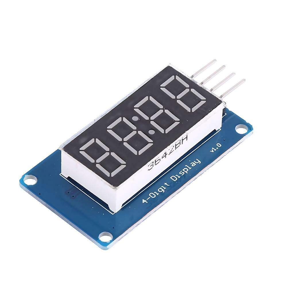
HiLetgo 4-Digit LED Display TM1637
Leave a Reply