
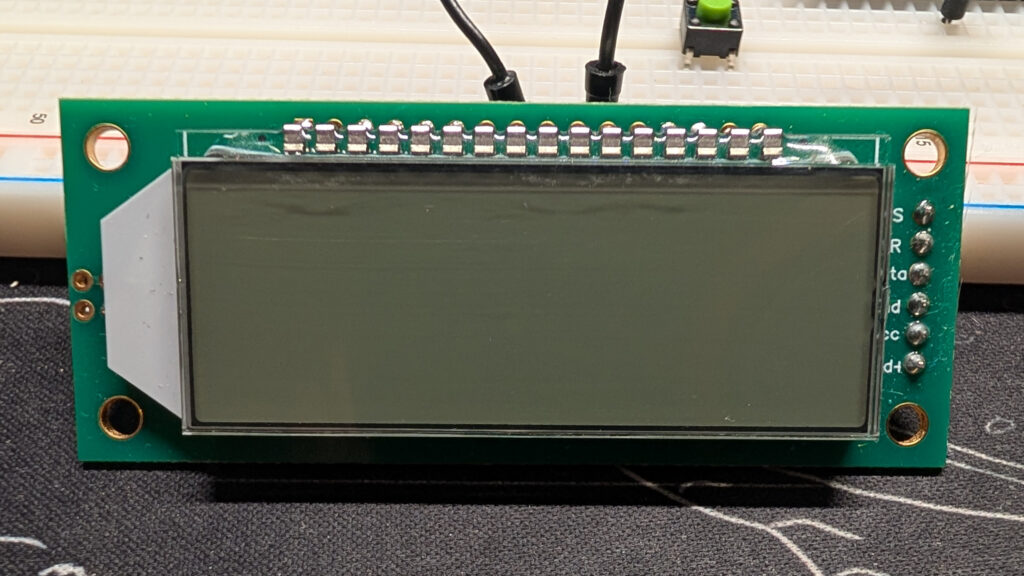
The time has finally come to start working with TN LCD displays like the ones the clock is going to use. And as a bonus, the dev board I have uses the HT1621 LCD controller that I plan on using as well. Let’s do a quick recap to see how we got here.
The recap episode
These hijinks began with getting a 5161AS single-digit segmented LED display to output numbers. Looking back, it wasn’t a particularly hard project, but we did learn how to look at data sheets and how to pick out the right resistor for the part we want to power. Wrapping it up, we wrote some simple code to make everything work, the spirit of which still haunts our latest projects.
Next up we tackled the 5461AS 4-digit display and put together a manual multiplexer. In order to recover some of the pins that the 5461 demanded, we learned what a shift register is, how to incorporate one with our 5461, and how to chain two or more of them together.
After that success we dove into our first truly complicated data sheet when we learned about the TM1637. Having gotten a handle on that, we jumped right into bit banging some life into it without any fancy libraries, just brute force.
That’s a good bit of skill to have put under our belts!
The Holtek 1621 LCD Controller
Much like the TM1637 we were playing with last time, this HT1621 is incorporated into a development board, this time with a 16-pin, 6-digit, 48-segment LCD instead of a 12-pin, 4-digit, 32-segment LED display.
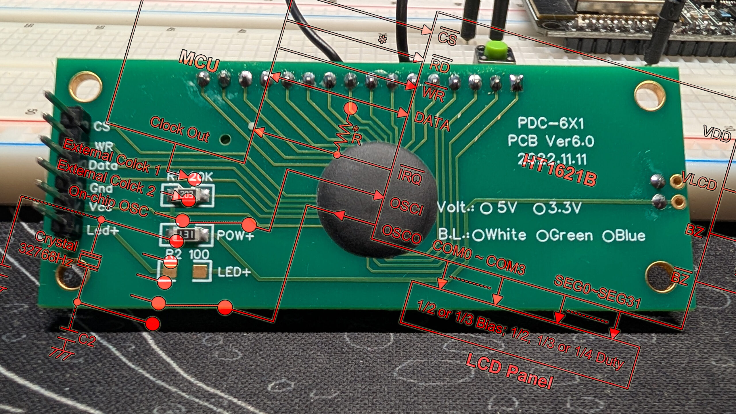
LCD’s are a different beast, so there are some new things to learn as we navigate these waters, but nothing so impossible we can’t overcome it. Let’s start by looking at the dev board to see what pins there are.

Pins on the HT1621 LCD driver
Instead of four pins, like on the 1637, this one has six, but we’re only going to use five of them. You can see from the back of the board that the Led+ pin doesn’t go anywhere, and if you connect Gnd and Vcc, the backlight will light up. That means we don’t have any control over our backlighting unless we want to play with some surface-mount components. For now, let’s see what those other pins do.

Vcc and Gnd we already know go to power and ground. The description of the product I bought on AliExpress listed this as being rated for 5 volts but it runs fine on the 3.3 volts from the ESP32.

First on the list is CS, or chip select. Remember, that overline indicates that CS is active when it’s pulled low. We pull CS low to tell the 1621 we’re about to send some commands.

We can skip over the RD pin, since even if we were interested in reading our display data, we don’t have access to the RD line. WR, on the other hand, is essentially our clock. This is slightly different from other clock pins we’ve used in the past in that this one is actively high, so we need to pull it down in order to bring it back up. In other words, we’ll need a dip instead of a pulse.

DATA works just like all the other serial input pins we’ve used. We pull it high or low based on the bit we want to send, then dip/pulse the WR pin to register the data. Those are the only pins we have direct access to, so let’s figure out how to make this thing do something.
Commands on the HT1621 LCD controller

The first concept we should grapple with is the command prefixes. These are little 3-bit signals that we have to put in front of any commands we send so the 1621 can differentiate the subsequent signals it receives. Since we don’t have access to the RD pin, we only have to worry about Write (101) and Command (100).

Take a look at these command codes. Notice the bold bits in the front. Those are the prefixes we just talked about. They’re not technically part of the commands, but they do put them in context. LCD ON and LCD OFF should be self explanatory, just note that the X is an irrelevant bit and it can be set to either 0 or 1 and the 1621 won’t care. That makes the command to turn the LCD on 000000110.
COM stands for common and it indicates the number of common pins on the LCD screen. As for BIAS, fully explaining it is beyond our scope, but it basically indicates how many different voltage levels to use when driving the LCD. Getting an LCD to cleanly display the correct segments is a lot more complicated than on a segmented LED display, which is why you need a special chip to do it. Given that we don’t have a data sheet for the LCD display on this board, we just have to guess at these, but I’ve done the work and can tell you this display uses 1/3 bias (the most common) and has four common pins. That means the command to set our BIAS and COM is 001010010.

The last command we need to know before we start writing data is SYS EN which enables the system oscillator: 000000010. We need this to maximize the contrast on the display. LCDs are powered by alternating current (another reason we need a special chip) and the waveforms of those currents need to be synchronized between segment and common pins to make everything work right. The system oscillator is what allows that to happen.
Timing diagrams for the HT1621 LCD controller
Now we know which pins do what, and we know the basic commands, let’s figure out how to input them.
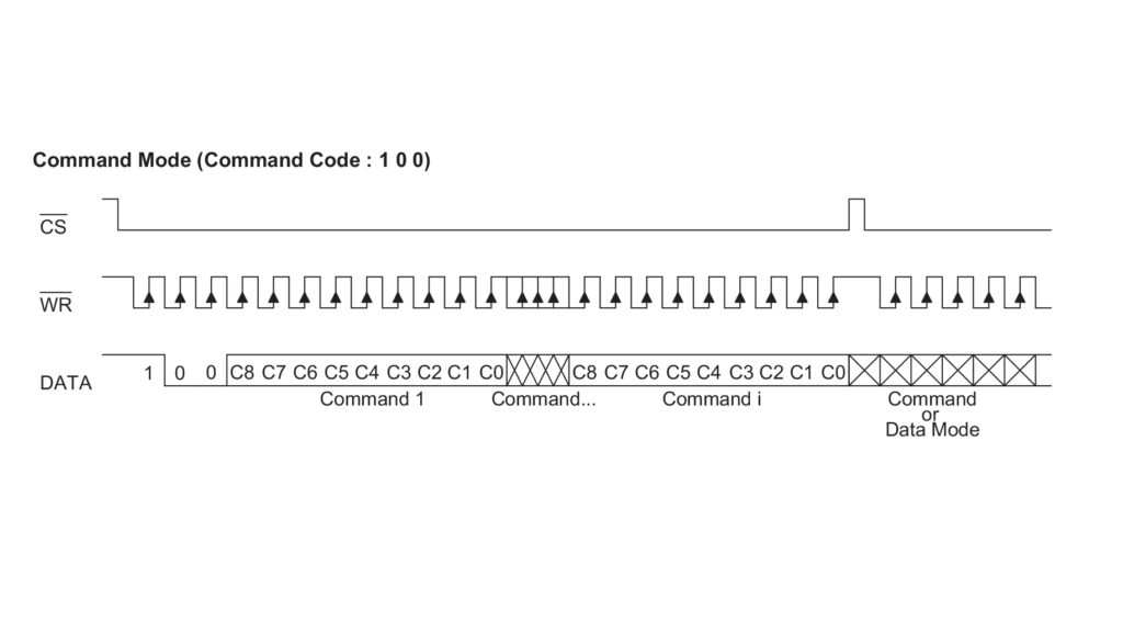
We’ve seen these timing diagrams before so let’s go over the important details.
- Up top we have the CS pin signal. The 1621 pulls it high by default and we pull it low when we want it to start listening.
- Next is the WR signal, our clock. Just like the CS pin, it rides high and we have to pull it low. When we let it go back up the chip reads the signal on the DATA line.
- The important thing to take away from the DATA line is that the 1621 expects to receive its 9-bit commands starting with the most significant bit, i.e. the left-most one.

Just as with the TM1637, there are two ways to write to the 1621: direct address and successive address. To add data in direct access, we have to specify which memory block to write to for each command. For successive access, we specify the first memory block we want to write to, then every subsequent data packet we send goes to the next memory block.
Before we move on, notice that the address is sent starting with the MSB (left to right), while data is sent starting with the LSB (right to left). We’re going to have to account for that when we send our data.
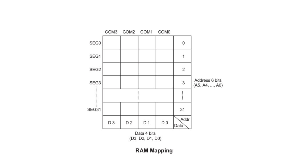
Looking at this diagram of the 1621’s memory and comparing it to the timing diagram, we can start to envision how sending segment data will work. One thing to be aware of is that addresses are represented with 6 bits even though there are only 32 of them, that means your addresses will always start with a leading 0: 000000–011111 = 0–31.
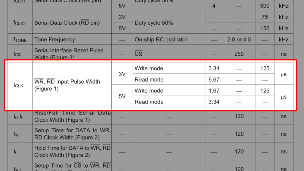
The last thing we need to know before we start banging out some code is pulse width: the time our WR pin needs to be high or low before returning to its previous state. On the previous chips we’ve worked with, the minimum pulse width was so low that we didn’t have to worry about it, but with the 1621 at 3.3 volts, the pulse width is potentially over 3 microseconds. Two digitalWrite() calls on an ESP32 happen in under a microsecond, so we’ll need to build a slight delay into our code.
So, with all that in mind, here’s what a basic data transaction with the HT1621 looks like:
- Pull CS low to enable the chip
- Send command (
100) code to set bias and duty cycle:001010010 - Send command (
100) code to enable the system oscillator:000000010 - Send command (
100) code to turn on the display:000000110 - Pull CS high to disable the chip
- Pull CS low to enable the chip
- Send write (
101) code to indicate starting address:000000 - Send data
- Pull CS high to disable the chip
That’s a bit more work than we did for the 1637, but not by much. The 1621 will be a piece of cake.
Read next …

Read previous …

Buy somethin’ will ya?
If you like what I do, send me $1 to help pay for the infrastructure!

2.4-inch LCD Module with HT1621 Controller
Leave a Reply